Attach a Teletype to a Computer
Introduction
I first learned about Teletypes, when I was contemplating about line endings in Windows. I was wondering why there are two bytes at the end of each line instead of just one. The newline character (0x0a) made sense, but what the heck is a carriage return (0x0d)?
So I googled and found out that teletype machines, initially used for telecommunication, were also used to interface with computers and they actually require two mechanical operations for a new line: First the carriage, the mechanical part that prints the letters, is returned to the start position and then the paper roll is advanced by one line. The bell character (0x07) has also its origin in the teletype machines: There is an actual bell that can be ring to catch the operators attention.
I was fascinated how these machines work and that their footprint is still present in todays computers. Be it the carriage return, new line and bell characters, the serial communication or the tty devices on *nix systems, we use every time we open a command prompt.
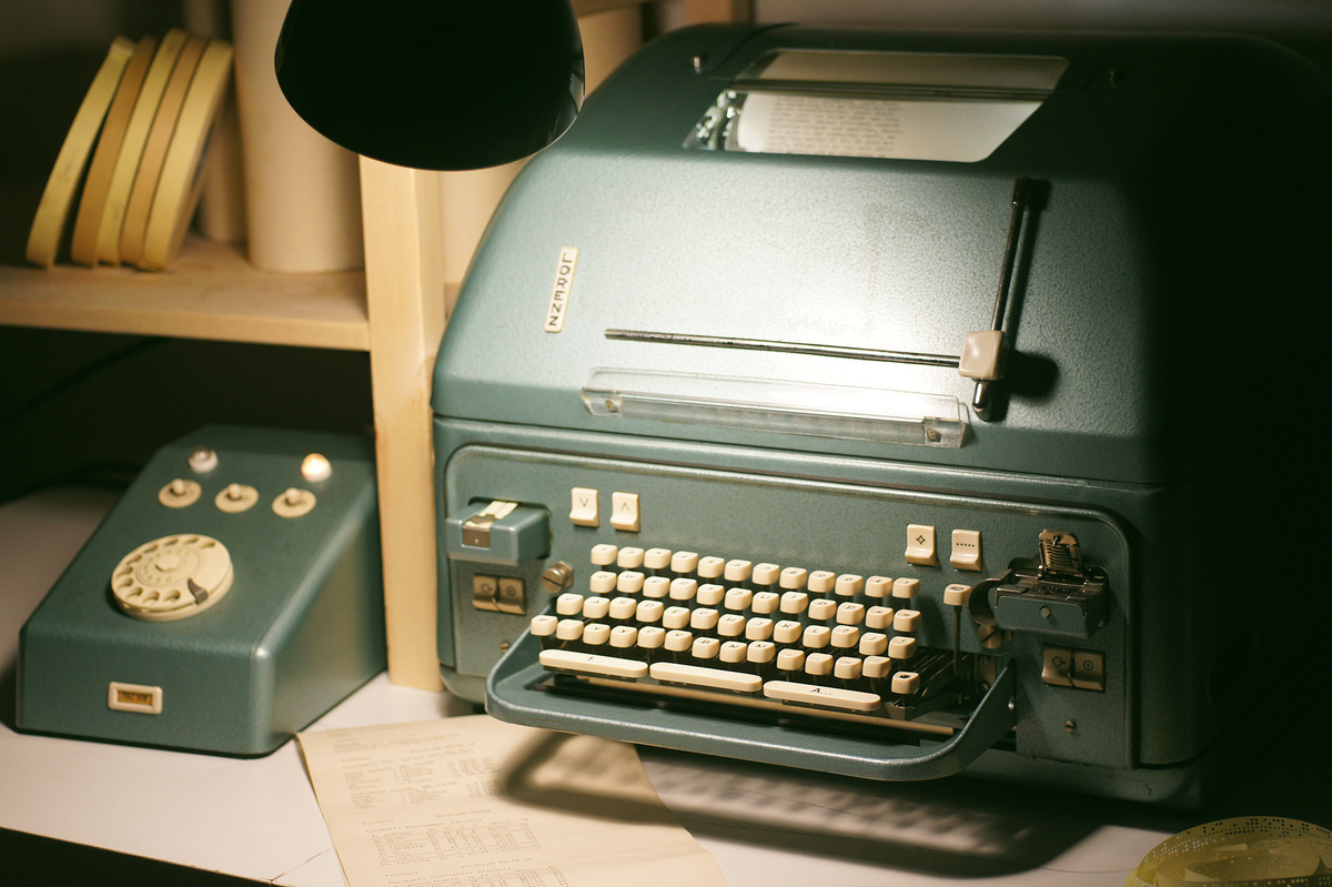
In September 2021 I was able to obtain a very nice teletype model, the Standard Elektrik Lorenz Lo15. Many thanks to the previous owner DL8GBR, who entrusted me with his machines 👋.
I only had to replace the motor capacitor and some old damping foam that turned into gunk. But apart from this the machine worked very well.
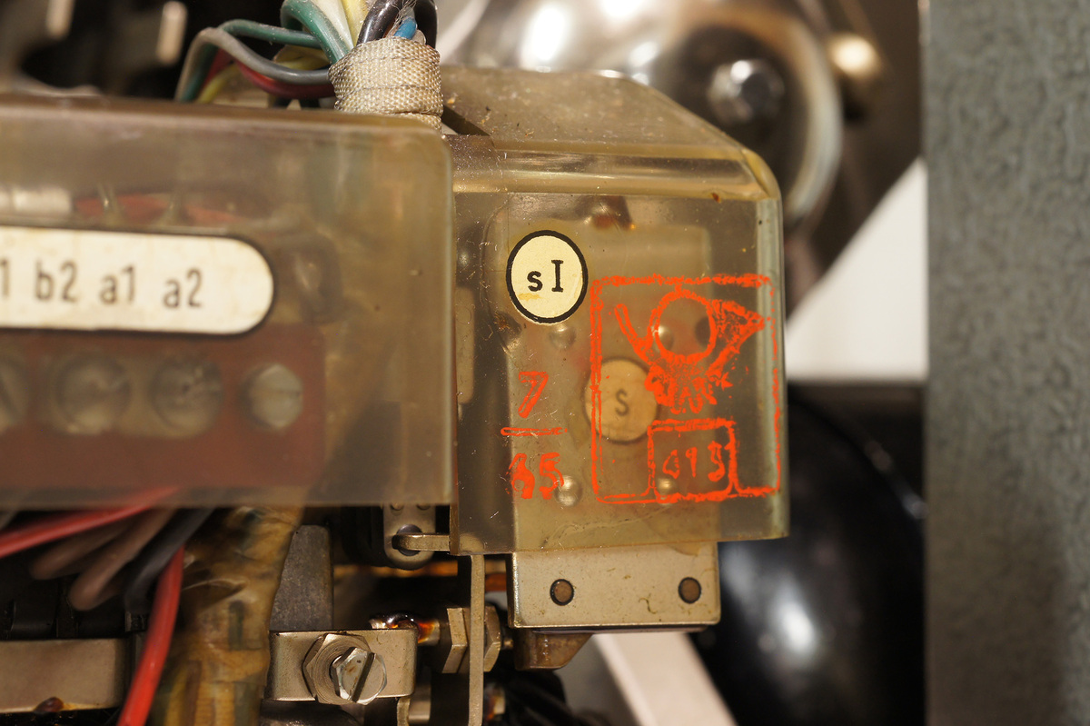
The machine design was licensed to Lorenz from the American Teletype company and is based on their Model 15. I think my machine was build around 1965 but I'm not 100% sure. The motor capacitor has the date mark "11.64" and the first authorisation stamp from the German post office on the machine reads "7/65".
How the Machine Works
Teletypes were used to transmit text messages across large distances, one could say its the successor of the Telegraph and predecessor of the Fax. Messages are transmitted by opening and closing the electrical circuit between two machines quickly. Mine is configured to switch 45 times in a seconds, therefore running at 45 bauds. The baud rate can be changed, by adjusting the speed of the motor of the machine.
The motor runs off mains electricity (230 Volt AC) but the communication circuit operates from 60 to 120 volts DC, which has to be provided by an external power supply.
Originally this was done by the remote switching unit, the device with the rotary dial. It was used to connect the teletype to the Telex network of the phone company:
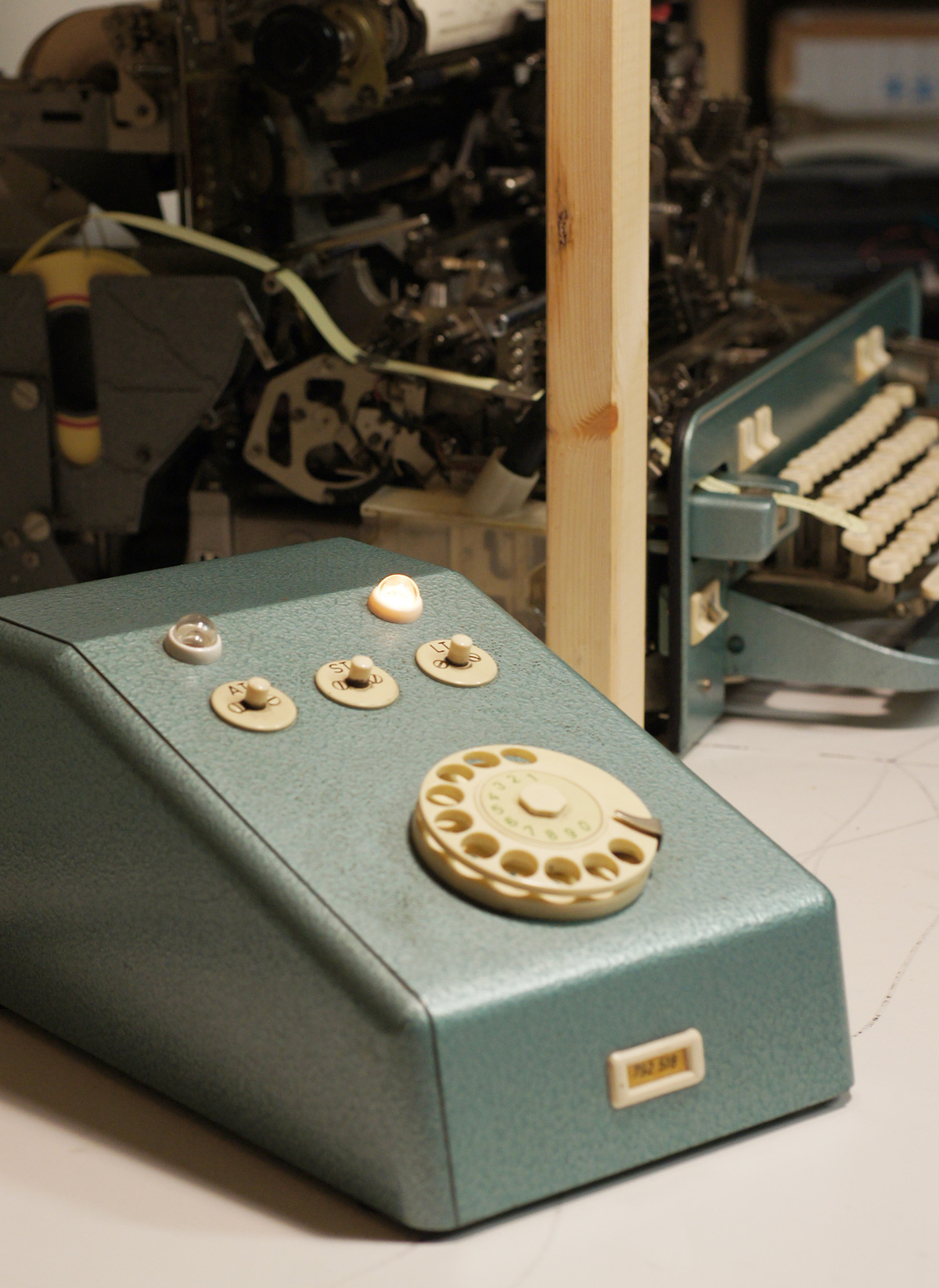
If a remote teletype would call, the remote switching unit would turn on and off the motor and the communication current to the teletype, thus the name.
To call another teletype, the "AT" switch was pressed and the according number was dialled in. As soon as the remote machine would answer with its unique identifier, the message could be sent through. To end the call, the "ST" switch was pressed.
The "LT" switch was used to power the motor and the communication circuit locally, without being connected to another subscriber. This allowed for example to prepare a message on punch tape and send it later on.
In Switzerland, there is no commercially operated Telex network available anymore, but there is a free and globally available service operated by enthusiasts: The i-Telex system. It allows to communicate with other teletype machines over the Internet 💪!
Teletypes use serial communication very similar to what we use today on computers. When current flows, it's called a mark (logical 1) and when no current flows, it's called a space (logical 0). Most teletypes use a 5 bit encoding scheme called CCITT-2. Here is an scope shot of transmitting the letter "Y" (10101):
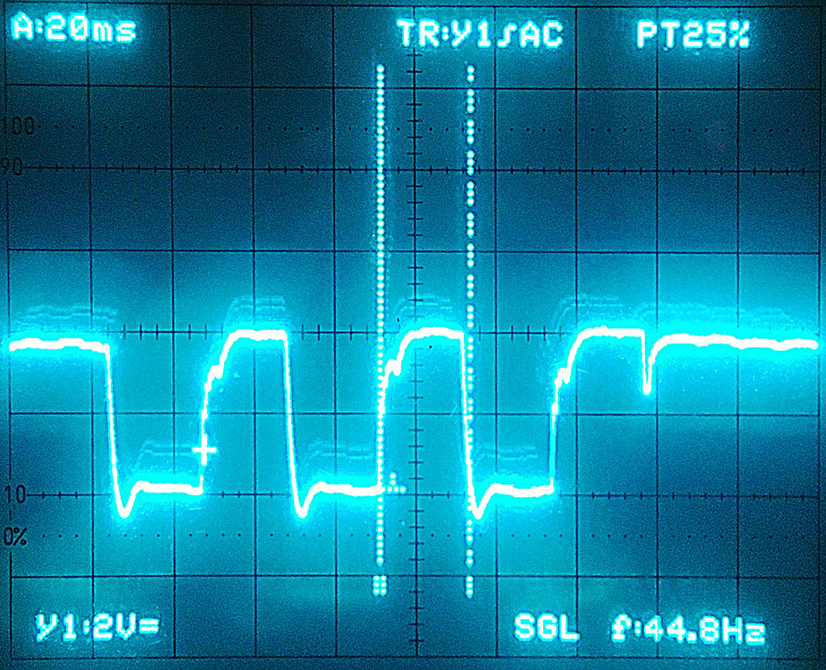
The start bit is when the communication line goes low for the first time, then the 5 data bits follow and then the line goes high for at least 1.5 bits, which is called the stop bit. The idle state of the line is high. So if you don't connect the machine and run the motor, it will continuously clatter, as it is registering all zeros, which is the blank character. This lets you immediately know that something with the communication line is wrong.
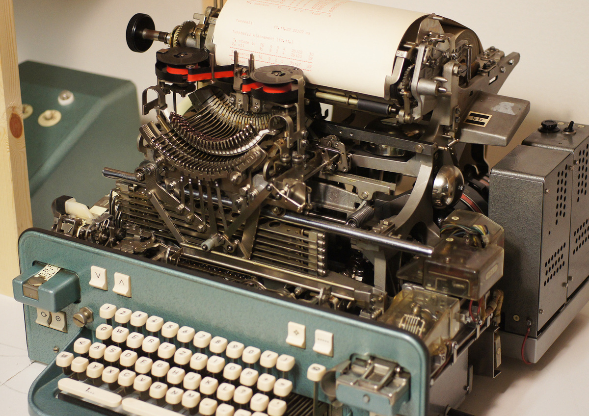
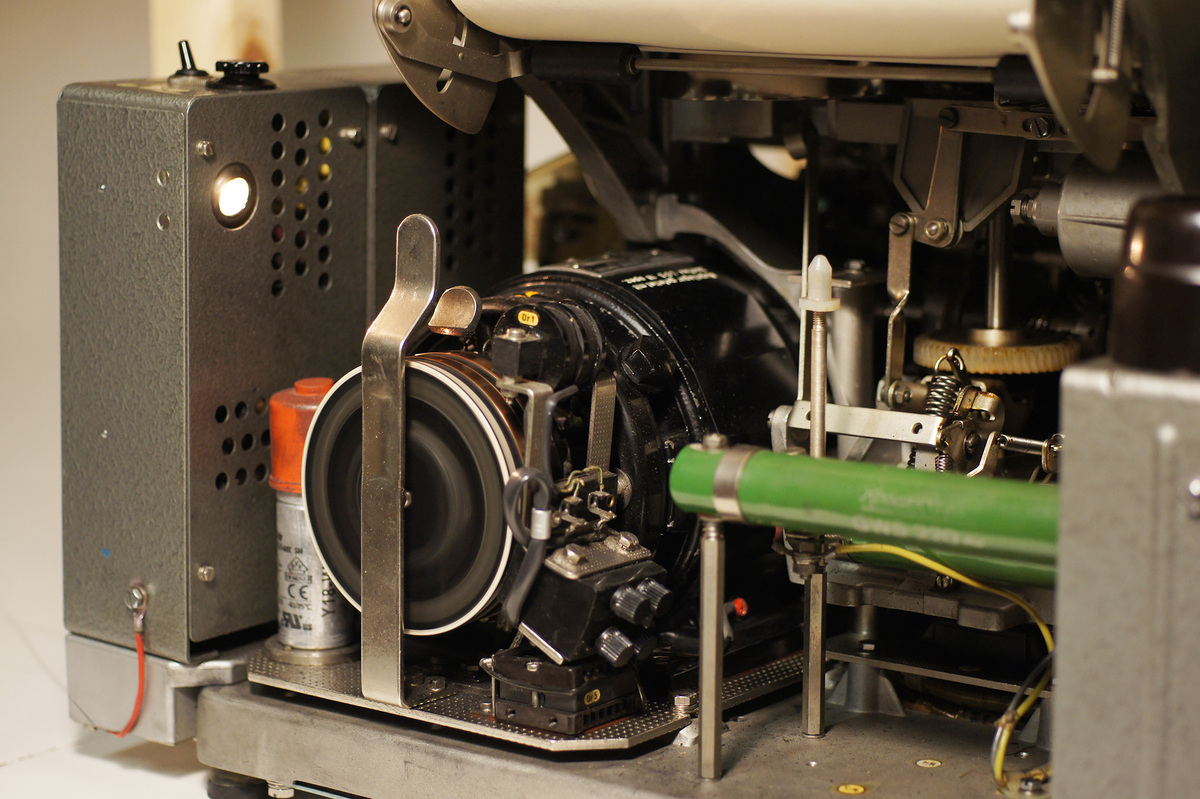
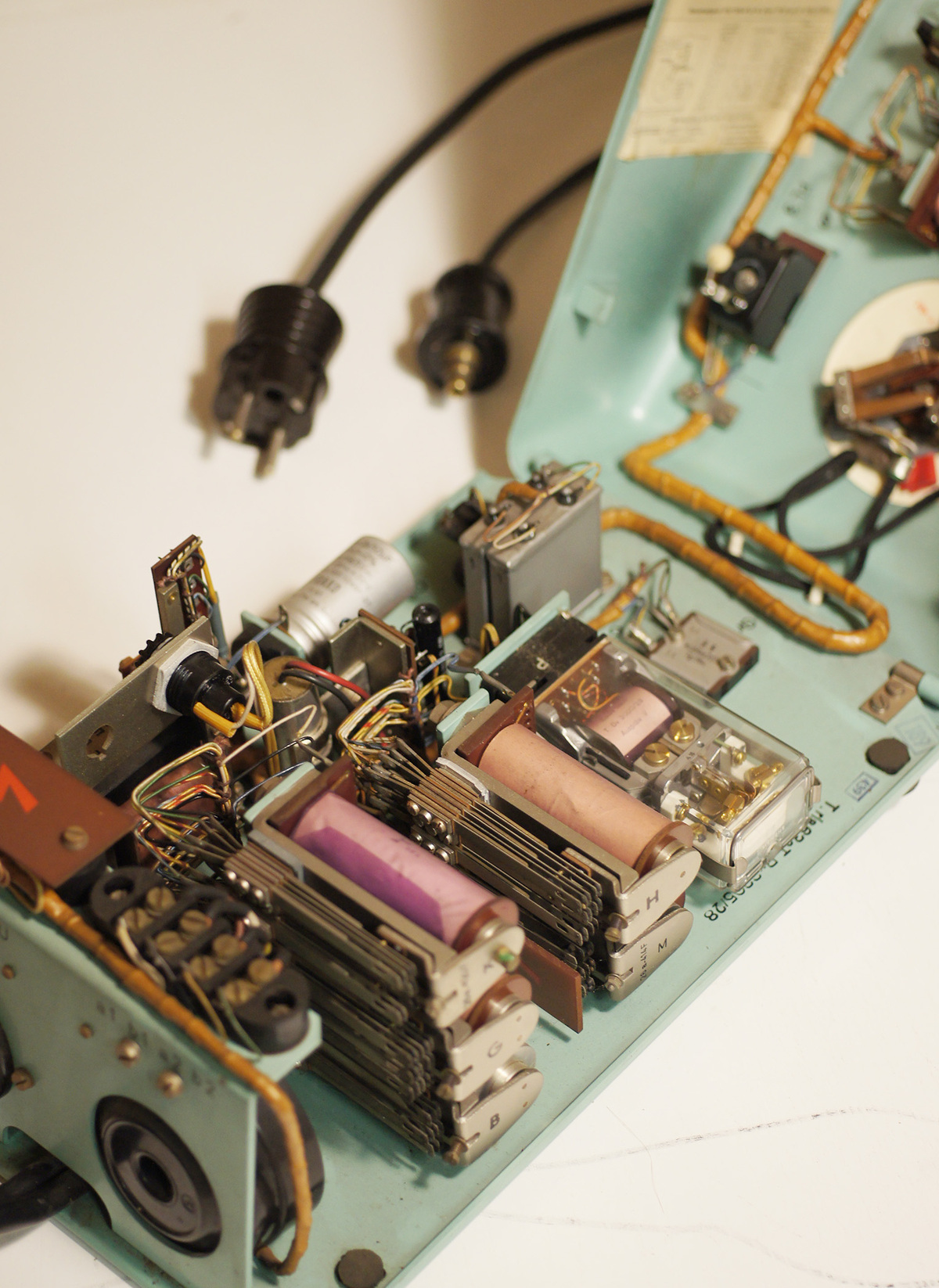
The electrical impulses can be created and received by the machine. Therefore it has two circuits: The receiver and sender circuit.
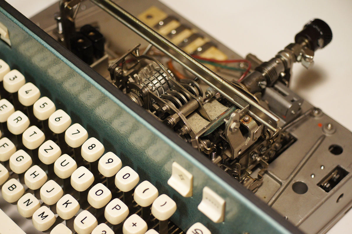
The sender consists of the keyboard that actuates 5 switches, that turn the communication line on and off according to the pressed key.
The receiver consists of two magnets (the purple objects, on the lower left), that translate the electrical impulses into mechanical movement, which then selects the correct character and prints it.
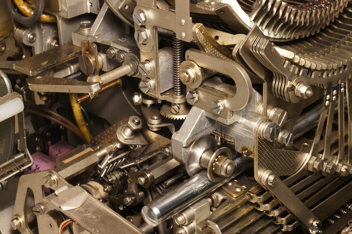
Normally the sender and receiver circuits are connected together, so if you press a key, it gets printed immediately. This configuration is called half-duplex, because only one teletype can send at the time. The machine can also be wired in full-duplex mode, meaning the sender and receiver circuits are separated, which allows two teletypes to send at the same time.
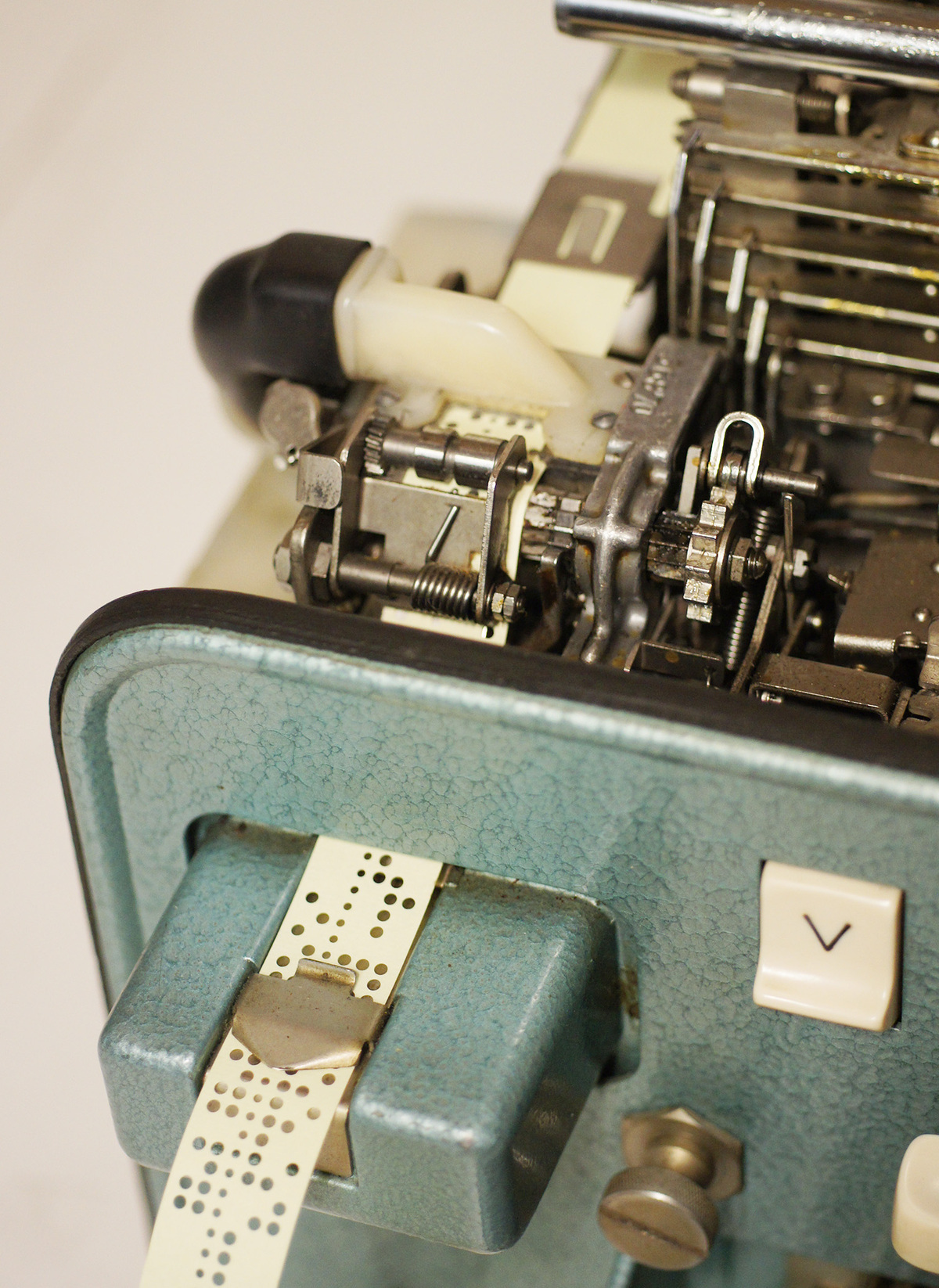
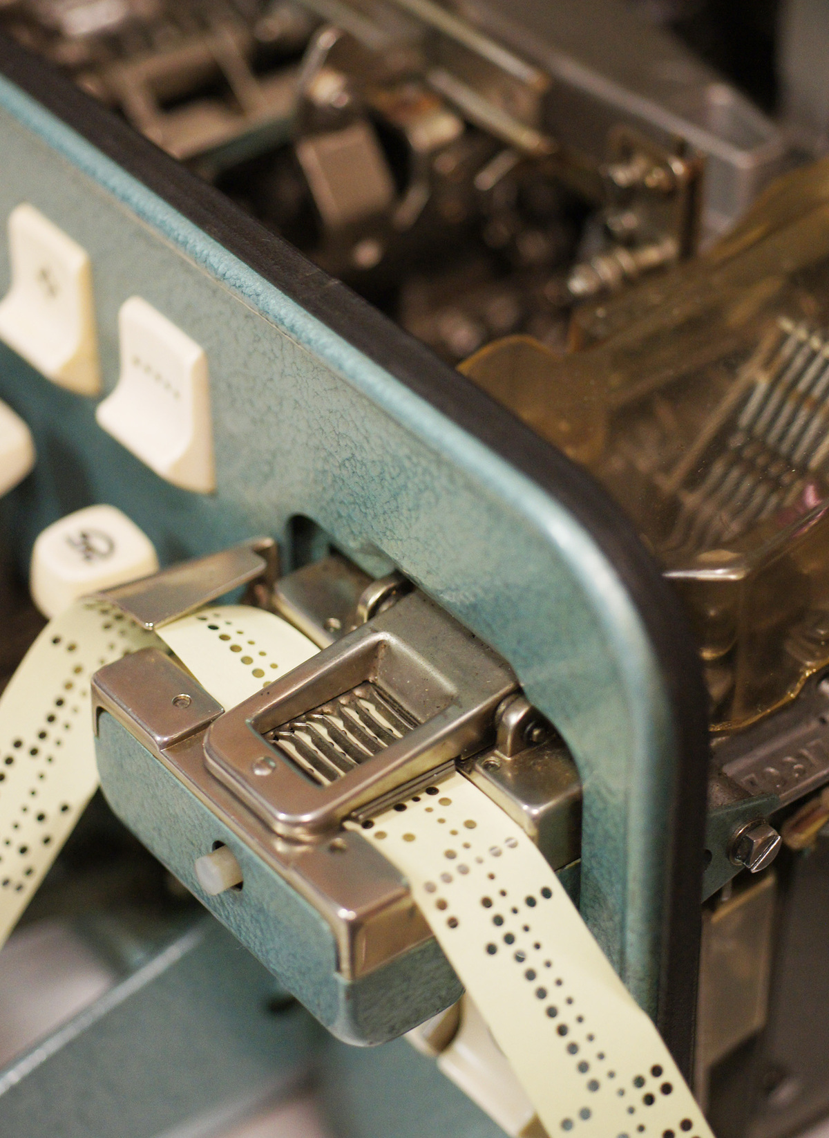
My machine also as a tape puncher and reader:
If you want to know all the mechanical details about the machine, I can recommend this Youtube video. It's about the Model 15 of the Teletype Company, but the Lorenz Lo15 I have, works almost identical.
I also made a video, to show my machine in operation and capture some of its awsome steampunkness 😉:
How The Converter Works
To do anything useful with the machine, I decided to build a TTY to RS232 converter, so I can connect the machine to my computer.
This is what I came up with 🤩.
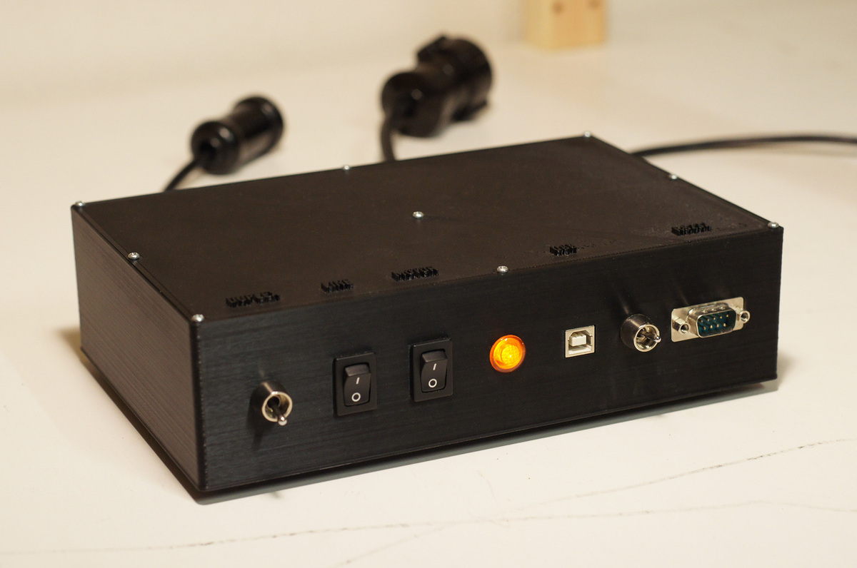
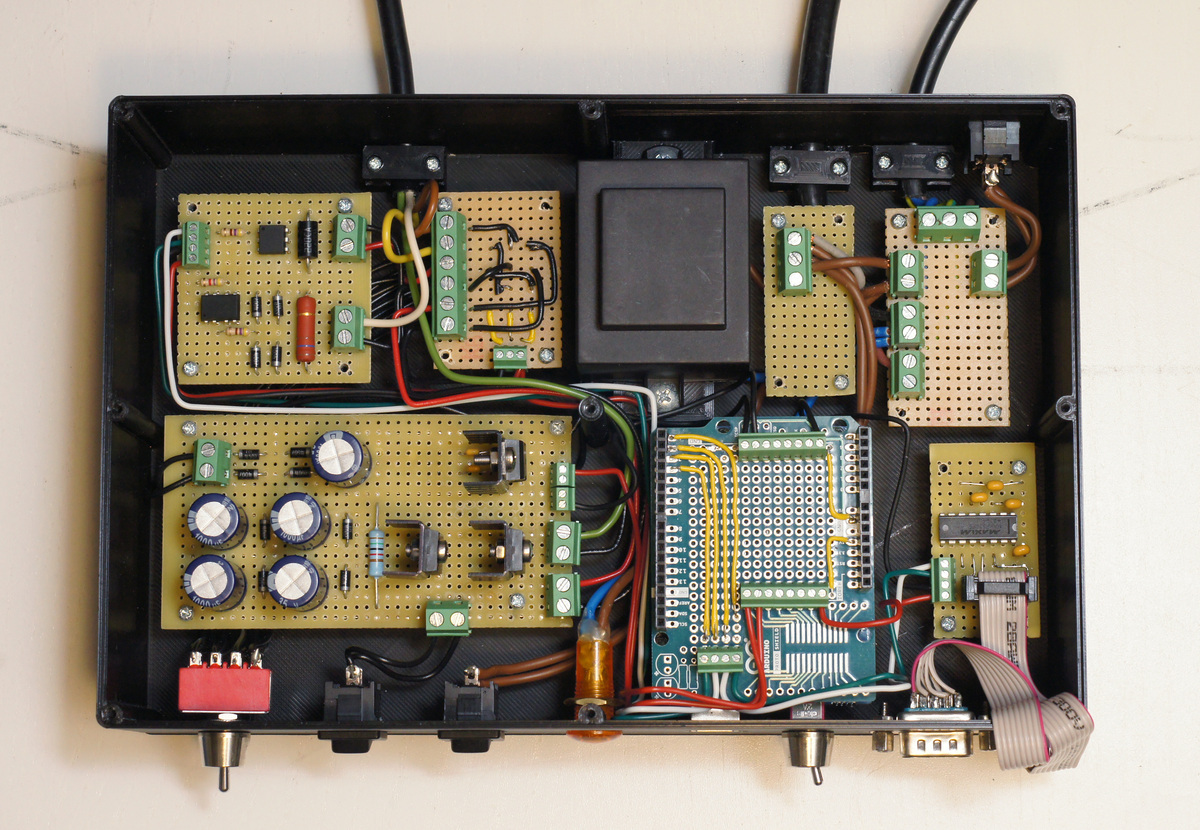
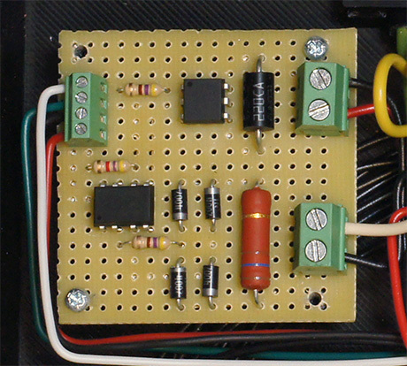
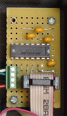
On the top left there is the interface board between the high voltage communication line and the ttl level voltage which is based on Eric Volpes Design. For receiving, it uses an optocoupler to detect the state of the communication line. For sending, it uses a solid state relay to break or connect the communication line.
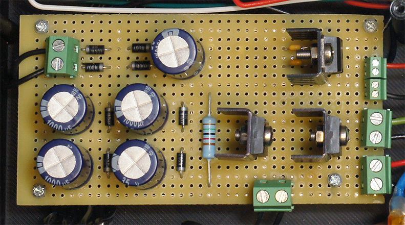
Below it is the power board. It is more or less based on the i-Telex power board design created by Fred Sonnenrein. The power board uses a voltage multiplier circuit, to step up 12 volts AC to 80 volts DC. It has two high voltage outputs, one for the teletypes receiver and one for the sender. They use 30 W power resistors with heatsinks to limit the current to 40 mA. The resistors have quite a small footprint but unfortunately also get quite hot. There is also a switch to turn on and off the communication current on the front panel and a 5 volt regulator, used to power the microcontroller.
The microcontroller itself is an Arduino Uno, that does the 45 baud 5-bit CCIT2 to 4800 baud 7-bit ASCII conversion. There are also some helper functions, like auto newline and local echo. It has a prototype board on top, that holds the cable connectors. I had to desolder the power jack to fit the Arduino into the case.
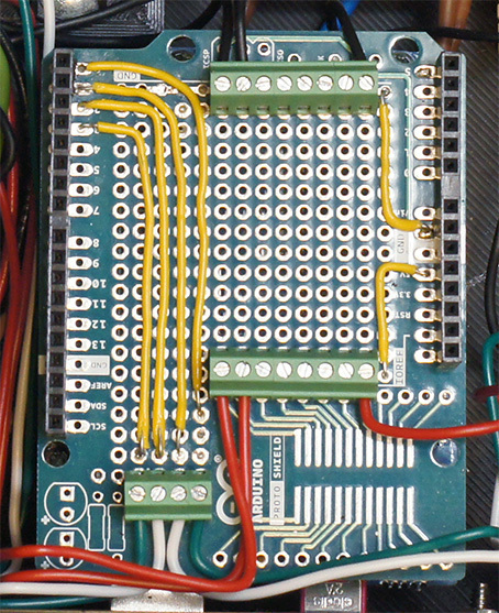
To the right is a MAX232 based TTL to RS232 converter, that connects with a ribbon cable to the DB9 port on the front. A switch between the MAX232 TX pin and the Arduinos RX pin is required to toggle between the Arduino onboard USB and the MAX232 RS232 connection.
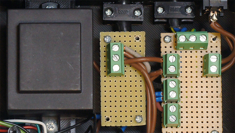
Above are two boards that are used to route the mains voltage to the 12 volt transformer and to the motor of the teletype. The motor can be turned on and off with a switch on the front. I also left room for a relay, that would allow the Arduino to switch the motor. The 12 volt AC transformer is on the left.
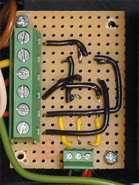
The last board is used in conjunction with a 4 pole switch on the front and is used to connect the communication line to the teletype. In the first position of the switch, the teletype sender and receiver are connected in series to the same high voltage output on the power board, resulting in a half-duplex connection. In the second position, the sender and receiver are connected each to their own high voltage output, resulting in a full-duplex connection. One of the poles is either connected to 5 volts or ground. This allows the microcontroller to detect the switch position, if required in future.
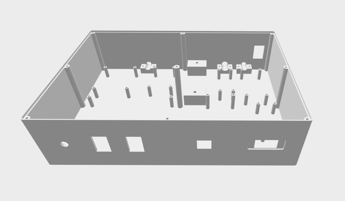
The case is made specially for this project. I designed it with Blender and printed it on my CR-10 and it took more than 24 hours to complete 🥱. I had to drill the holes for the power indicator light and the USB / RS232 switch afterwards, as these were afterthoughts.
The whole converter came out quite nicely and it also works very well.
However, some improvements could be made:
Power Board
The resistors on the power board waste a lot of energy and get quite hot. There are better solutions to generate the communication current:
Arduino Code
Currently, no input or output buffers are implemented. The code relies on the Arduinos internal serial buffer, which is only 64 bytes by default. This results in two issues:
- When data is sent too fast to the converter, only the first 64 characters are printed.
- The full duplex mode is not working perfectly, as characters can't be send and receive exactly at the same time.
Having Fun
Since 45 Baud is quite slow, there is actually not really a use case for having such a machine, despite having some nerdy fun with it 😉.
In following video, I connect the teletype to a Linux laptop:
Here I use the teletype as a terminal on a macOS machine and issue some commands:
And here I call a VT220 terminal from the teletype through a modem connection:
Project Files
You find the code, the STL files of the 3D printed case and some hand drawn schematics on my Github: https://github.com/nerdprojects/teletype-to-rs232